Project brief
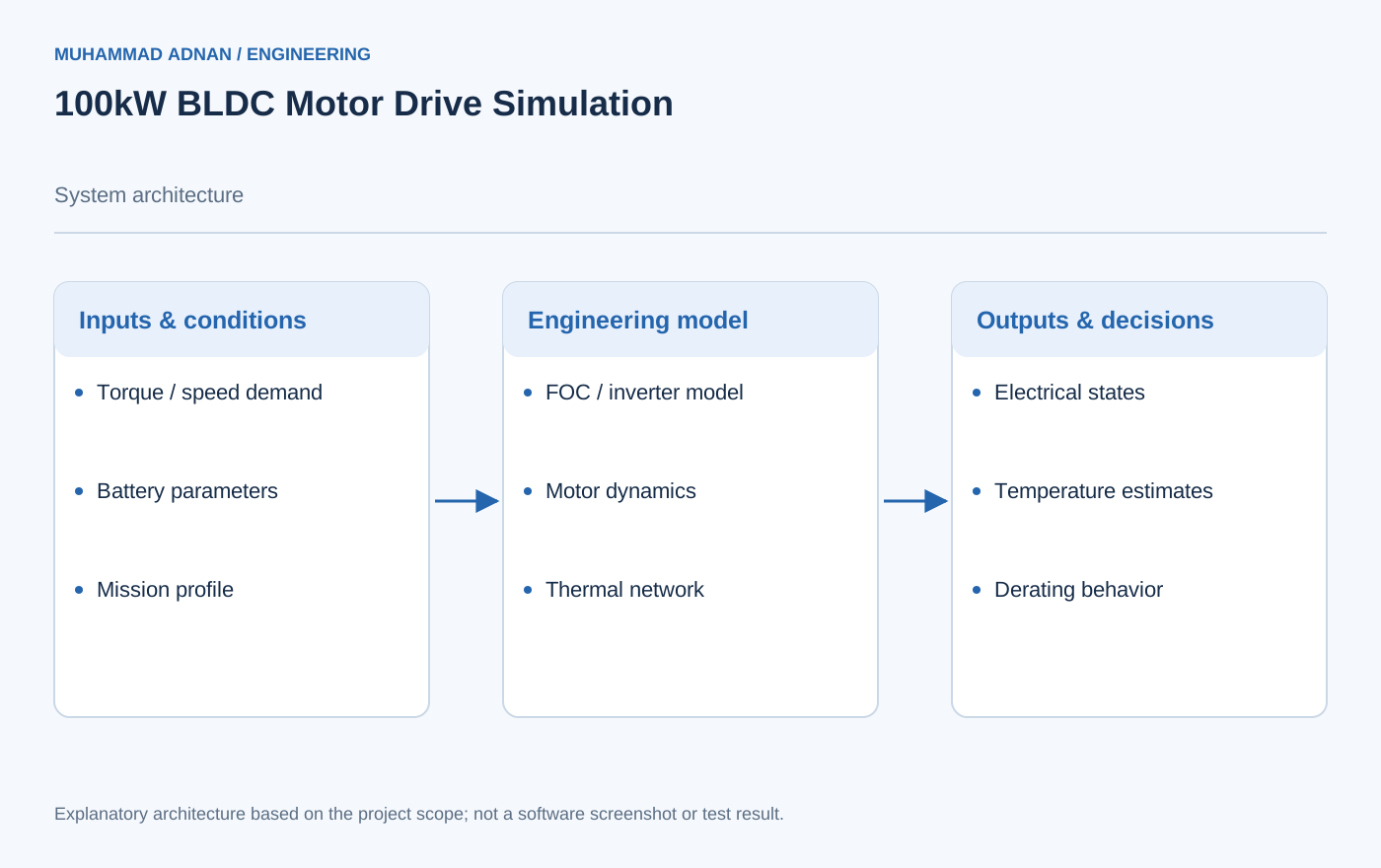
A complete Simulink/Simscape model of a 100kW BLDC motor drive for electric aviation propulsion applications. The model includes field-oriented control (FOC) with space-vector PWM, a SiC MOSFET inverter with detailed switching loss models, a 2RC equivalent circuit battery model, and full thermal network modeling for both motor and inverter to predict derating over mission profiles.
The case study describes an integrated simulation environment. Model architecture is shown without inventing time histories, loss maps, or measured performance.
The engineering challenge
Capture electrical, control, battery, and thermal interactions across an electric-propulsion duty cycle.
Engineering approach
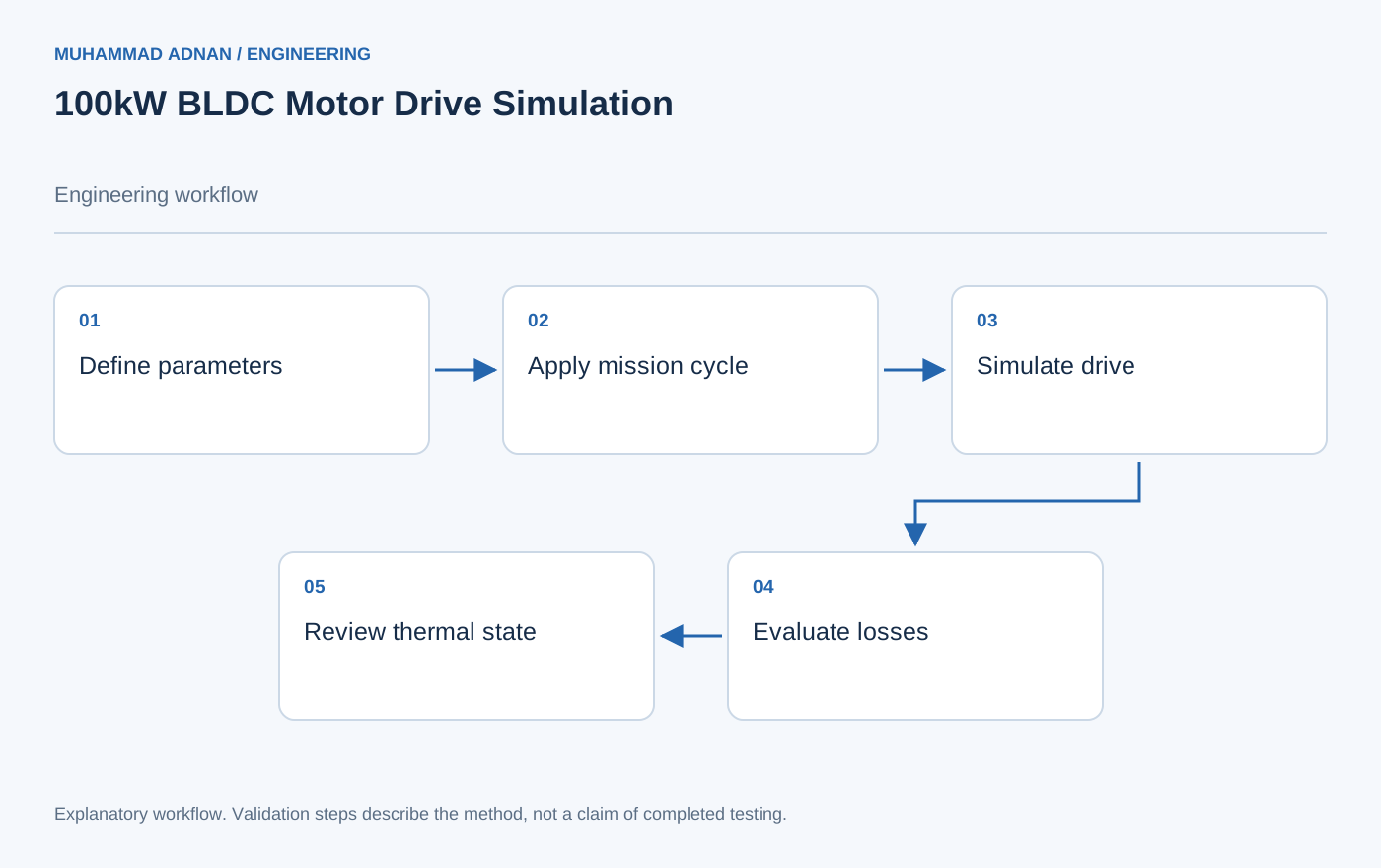
- Connect motor and inverter models to the field-oriented control loops.
- Include battery dynamics and loss-to-temperature relationships.
- Evaluate drive-cycle operating states through the integrated simulation model.
Features & capabilities
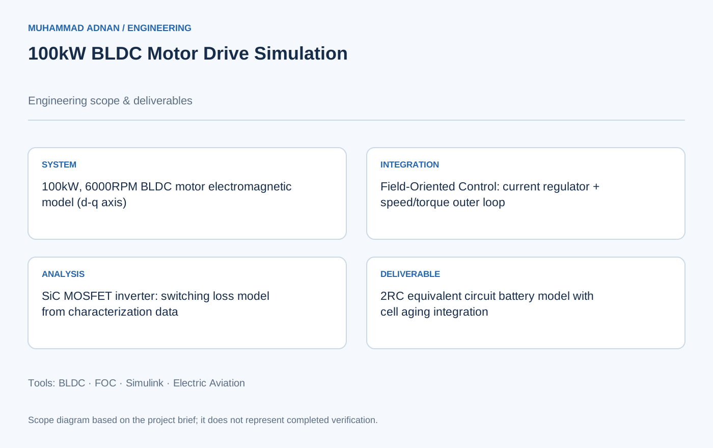
- 100kW, 6000RPM BLDC motor electromagnetic model (d-q axis)
- Field-Oriented Control: current regulator + speed/torque outer loop
- SiC MOSFET inverter: switching loss model from characterization data
- 2RC equivalent circuit battery model with cell aging integration
- Thermal network model: motor winding, stator, rotor + inverter junction/case/heatsink
- Drive cycle simulation: takeoff thrust, climb, cruise, descent profiles
- Hardware-in-loop deployment: dSPACE MicroAutoBox II tested
- Parameter identification from motor datasheet and FEA results
Software & engineering tools
MATLAB R2024a, Simscape Electrical, Simulink, dSPACE MicroAutoBox II, 1ms fixed-step solver