Project brief
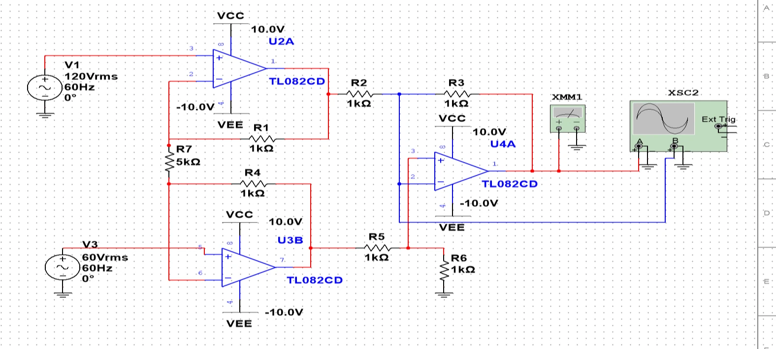
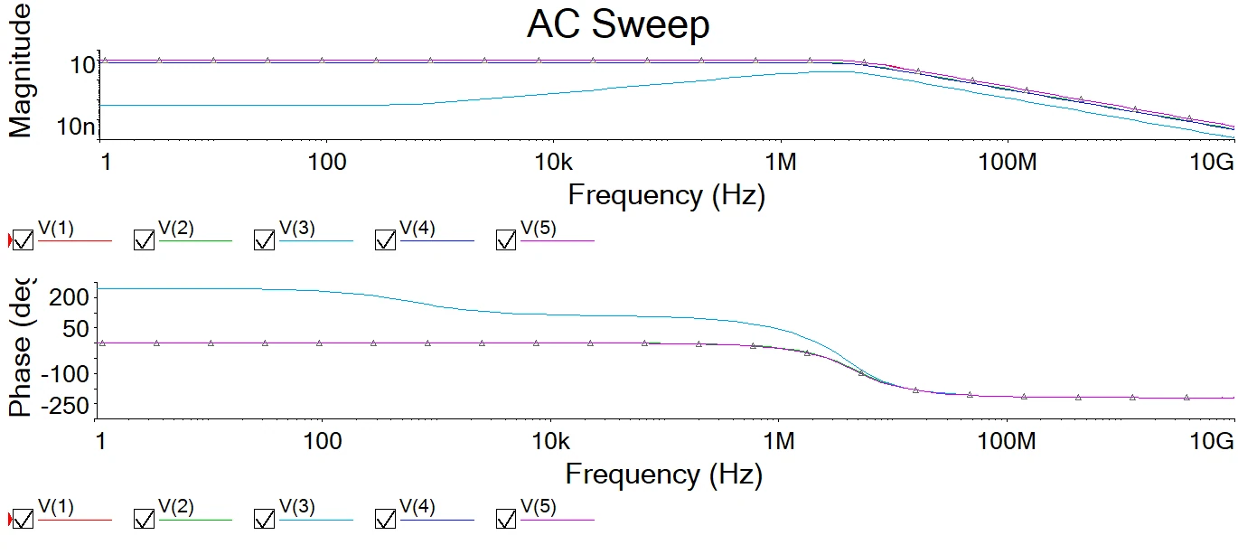
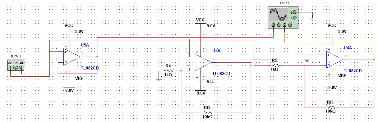
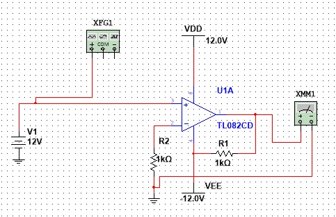
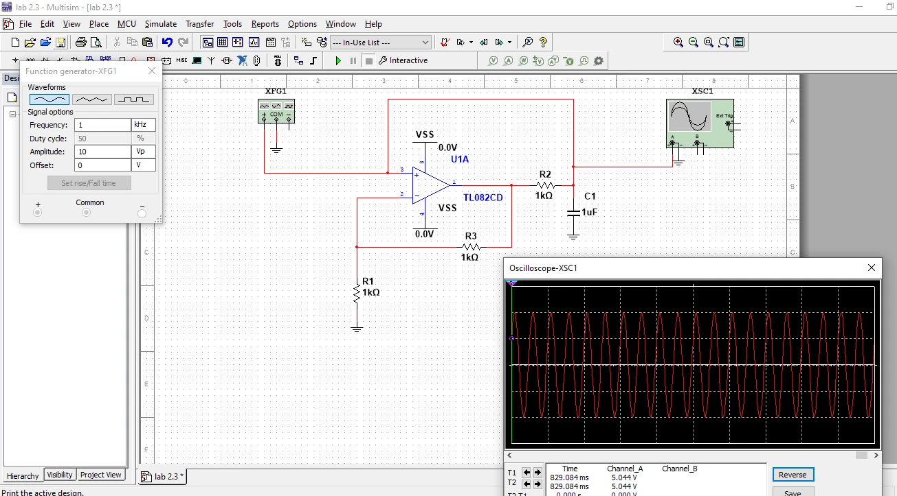
This analog-electronics study uses Multisim to build and examine operational-amplifier circuits through a sequence of increasingly complex configurations. The software evidence includes unity-gain arrangements, inverting and non-inverting amplifiers, negative-feedback circuits, two- and three-amplifier instrumentation stages, and regenerative-feedback switching circuits. Circuit schematics expose the component connections and virtual instruments, while AC sweeps, DC transfer plots, transient responses and oscilloscope windows show how the designs were investigated. The amplifier work considers gain selection, inversion, saturation, frequency response and phase response. The instrumentation section compares alternative differential-input topologies and discusses the roles of input impedance and common-mode rejection. Later exercises introduce a Schmitt-trigger arrangement, feedback-controlled hysteresis and multivibrator circuits for waveform generation. The report places these simulations within an ALSK board and oscilloscope testing workflow; the retained portfolio evidence focuses on the native simulation views. The project demonstrates breadth in schematic construction, instrument placement and analysis selection rather than a single finished electronic product. Its most useful output is a traceable set of circuits and response views connecting feedback structure with observed waveform behaviour. Design targets are kept separate from validated performance: several numerical derivations in the report require independent checking, so the demonstrated outcome remains a set of exploratory schematics and response analyses rather than confirmed circuit specifications.
The engineering challenge
Connect resistor networks and feedback topology to amplifier response, differential sensing and switching behaviour using appropriate simulation analyses.
Engineering approach
- Construct op-amp topologies and connect Multisim sources, meters and oscilloscopes.
- Inspect unity-gain and inverting/non-inverting feedback arrangements.
- Compare DC transfer, AC magnitude/phase and transient behaviour.
- Study two- and three-op-amp instrumentation configurations.
- Explore regenerative feedback, hysteresis and multivibrator waveform generation.
Results & observations
Native software plots document three complementary circuit-analysis modes.
Both configurations are represented by circuit and response screenshots.
The report includes linear amplifier networks and Schmitt-trigger switching exercises.
Multivibrator exercises extend the study to waveform and pulse generation; target values are not treated as verified measurements.
Features & capabilities
- Native Multisim schematics
- Virtual oscilloscope inspection
- AC magnitude and phase sweeps
- DC and transient analysis
- Instrumentation-amplifier comparison
- Regenerative feedback exploration
Software & engineering tools
Multisim, Virtual oscilloscope, Function generator, ALSK board workflow