
Project brief
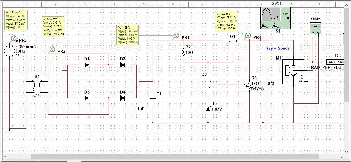
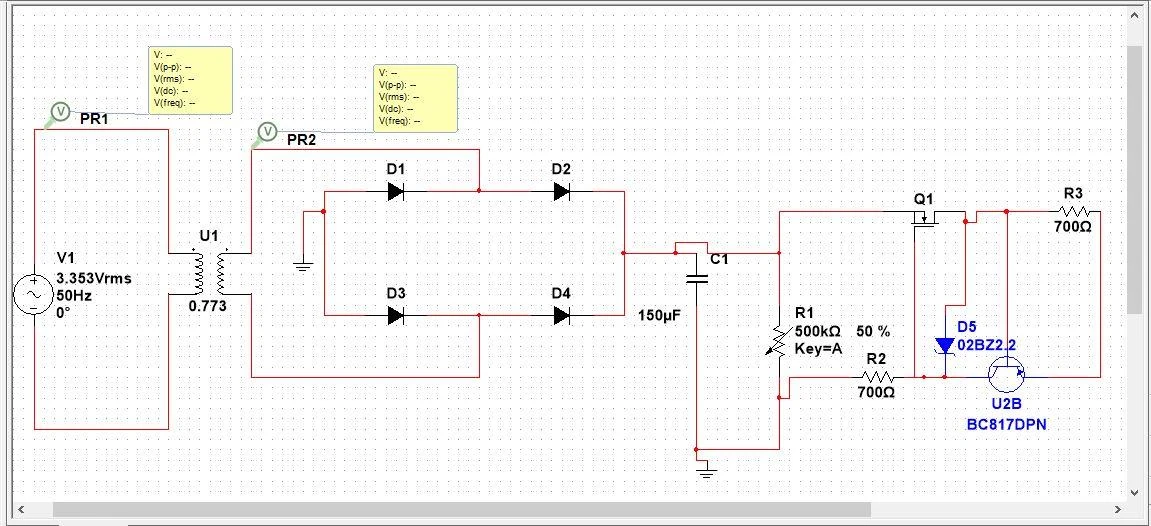
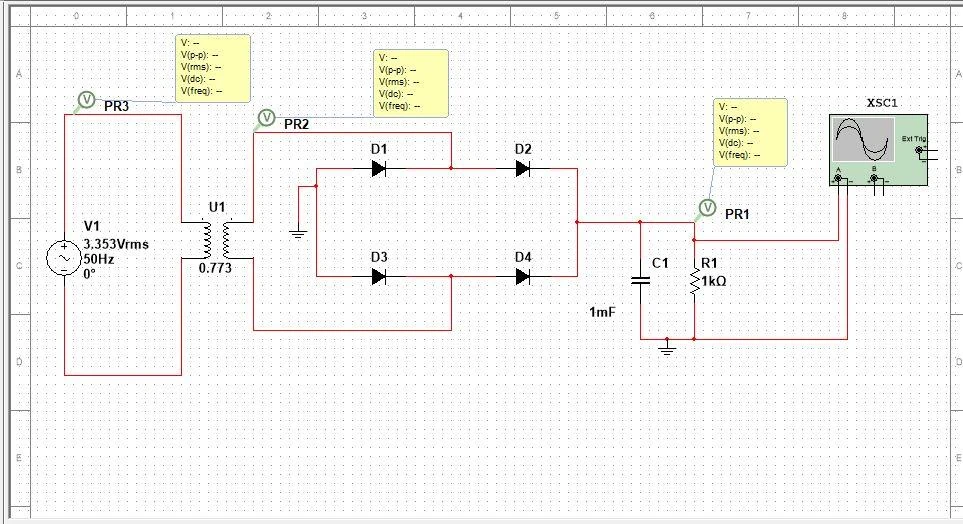
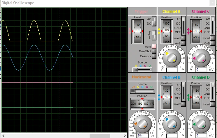
This circuit-design study progresses from diode rectification and voltage-regulator calculations to complete BJT- and MOSFET-based supply simulations. Early worked examples examine half-wave and full-wave rectification, diode voltage drop, peak inverse voltage, capacitor smoothing and Zener-referenced regulation. The supplied virtual-oscilloscope capture makes the input-to-output waveform change visible, while adjustable-regulator schematics show how transistor feedback and a potentiometer affect the output. The final Multisim sequence assembles an AC source and transformer, a bridge rectifier, a smoothing capacitor and alternative transistor regulator stages. Successive screenshots isolate the rectifier, add regulation and then connect a motor model with speed-conversion instrumentation. This staged presentation makes the signal and power path easier to inspect than a single final schematic. The report states an intended and obtained output range of 2.75–3.7 V and describes motor-speed variation through the regulated voltage. Those statements are treated as reported simulation outcomes: the artifact does not include a physical prototype photograph, load-regulation sweep, ripple benchmark or independently documented motor-speed dataset. Some written component values and calculations also differ between examples, so the brief avoids presenting them as a verified build specification. The project demonstrates analog modeling, virtual instrumentation and systematic assembly of functional circuit stages.
The engineering challenge
Translate rectifier and transistor-regulator theory into an inspectable supply model, then connect adjustable output voltage to a motor load without overstating the limited validation evidence.
Engineering approach
- Calculate rectified voltage, diode limits and smoothing requirements across worked examples.
- Inspect an original virtual-oscilloscope capture of the half-wave output and input signal.
- Model Zener-referenced adjustable transistor regulation with virtual voltage readings.
- Build the Multisim supply in stages: transformer and bridge, filtering, transistor regulation and motor load.
- Use virtual probes, an oscilloscope and speed-conversion instrumentation to describe the simulated behavior.
Results & observations
The final section compares two transistor-based regulator circuits in simulation.
Range stated in the report’s final results; no independent load or ripple sweep is supplied.
Source screenshots separate rectification, rectification plus regulation, and the complete motor-connected model.
A separate adjustable-regulator simulation displays this load voltage, with a reported 5.14 V Zener drop.
Features & capabilities
- Rectifier waveform inspection
- Zener reference and feedback
- Adjustable regulator models
- Alternative transistor stages
- Virtual voltage probes
- Motor-load and speed instrumentation
Software & engineering tools
NI Multisim, Virtual oscilloscope, Virtual multimeter, Analog circuit calculation