Project brief
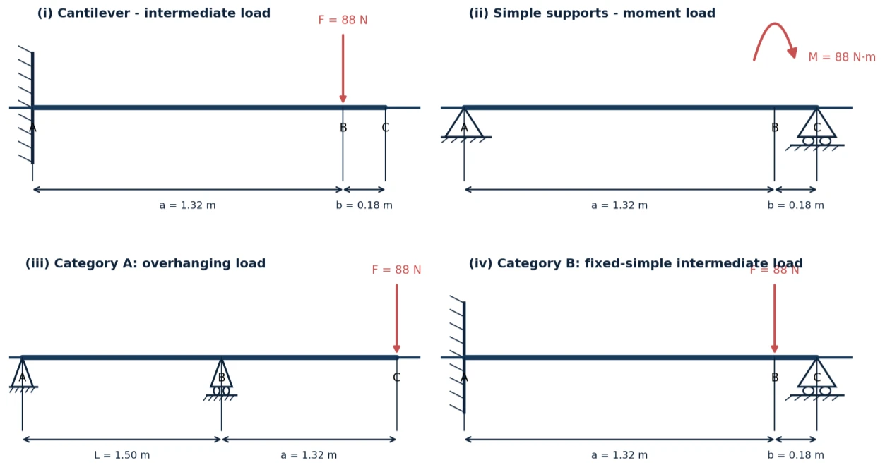
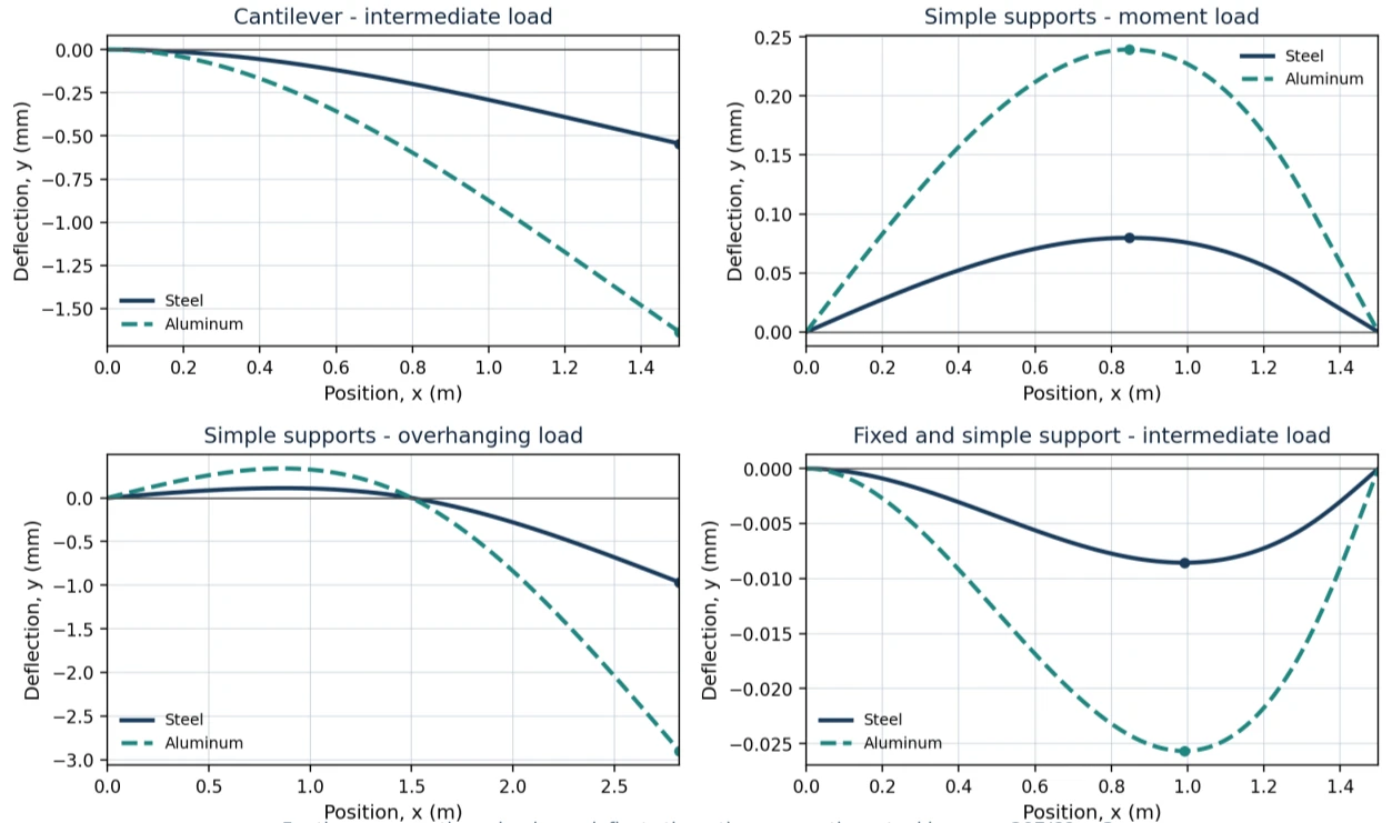
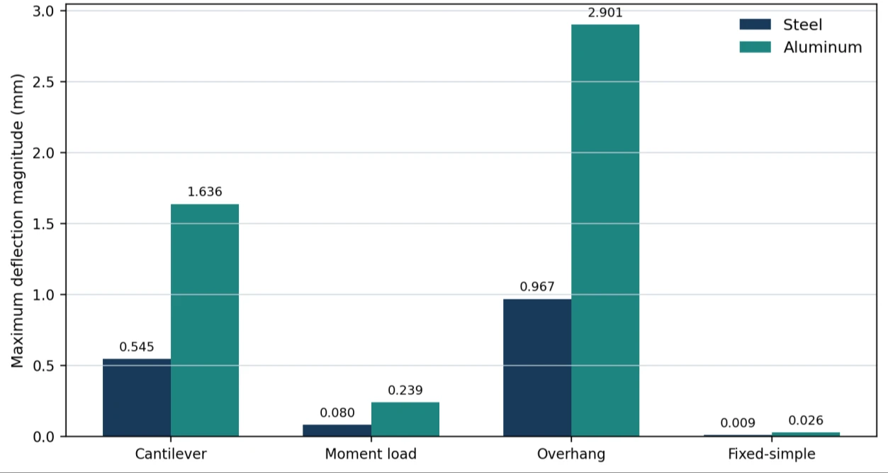
This project develops a reusable MATLAB calculation workflow for beam serviceability under several support and loading arrangements. Euler-Bernoulli theory and superposition provide the analytical basis for reactions, shear force, bending moment and transverse deflection. The model accepts material and section choices, evaluates the chosen load case, searches the computed deflection array for its maximum magnitude and location, and produces response diagrams. The reported comparison uses steel and aluminium with the same rectangular section, making the influence of Young's modulus easy to isolate. Four arrangements are studied: a cantilever with an intermediate point load, a simply supported beam with an applied moment, an overhanging beam with an end load, and a beam with fixed and simple supports. The overhanging arrangement has the largest reported deflection in both materials, while the additional support sharply limits displacement in the fixed-simple case. The study also shows the expected threefold deflection ratio from the selected elastic moduli. These results describe ideal linear elastic beams with constant stiffness; shear deformation, self-weight, support flexibility, dynamic effects and geometric nonlinearity are excluded. The portfolio evidence centres on the documented rectangular-section comparison, rather than separate command-window demonstrations that use different inputs.
The engineering challenge
Compare several beam boundary conditions consistently while separating the effects of geometry, support restraint and material stiffness.
Engineering approach
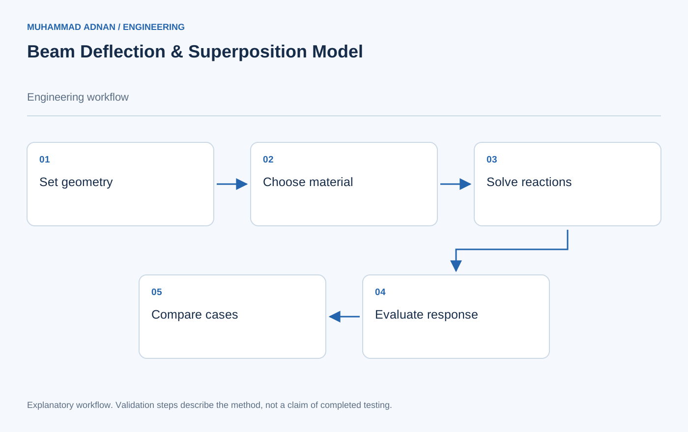
- Implement piecewise Euler-Bernoulli response equations for four loading cases.
- Use superposition and compatibility to solve the fixed-simple support case.
- Evaluate steel and aluminium with matching section geometry and span.
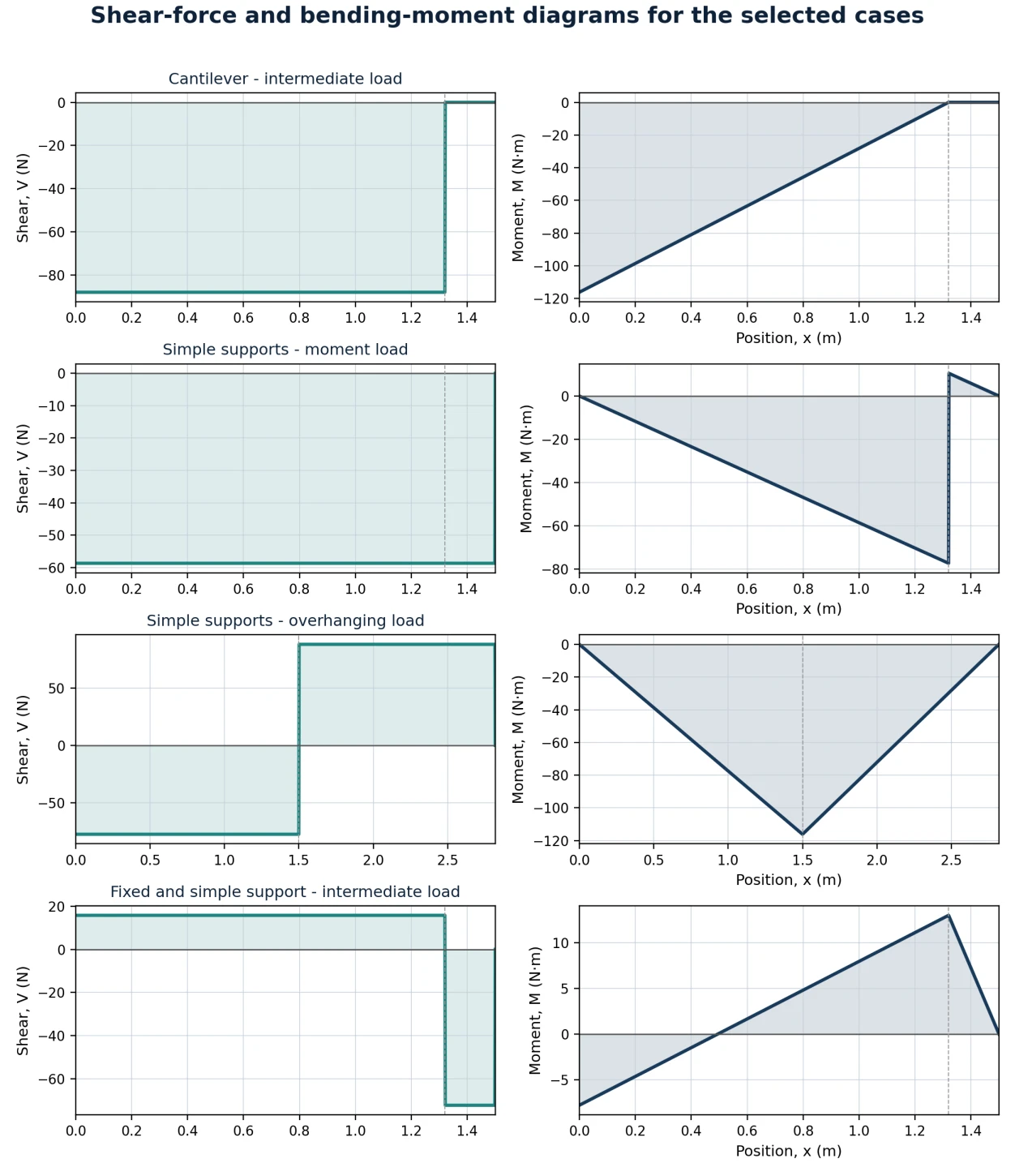
- Locate maximum absolute deflection numerically and plot deflection, shear and moment responses.
Results & observations
Largest steel maximum among the four reported cases; aluminium reaches 2.901 mm.
Smallest reported steel maximum; aluminium is 0.026 mm after rounding.
Aluminium-to-steel ratio from the selected Young's moduli of 69 GPa and 207 GPa.
Steel maximum at x = 1.500 m; aluminium maximum is 1.636 mm.
Features & capabilities
- Four support and loading cases
- Material selection
- Automatic section properties
- Maximum-deflection search
- Shear-force diagrams
- Bending-moment diagrams
Software & engineering tools
MATLAB, Euler-Bernoulli beam theory, Superposition