Project brief
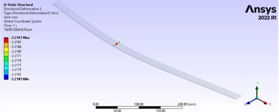
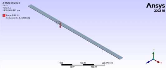
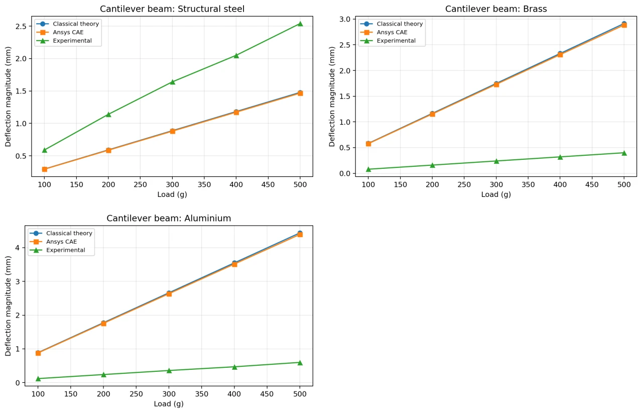
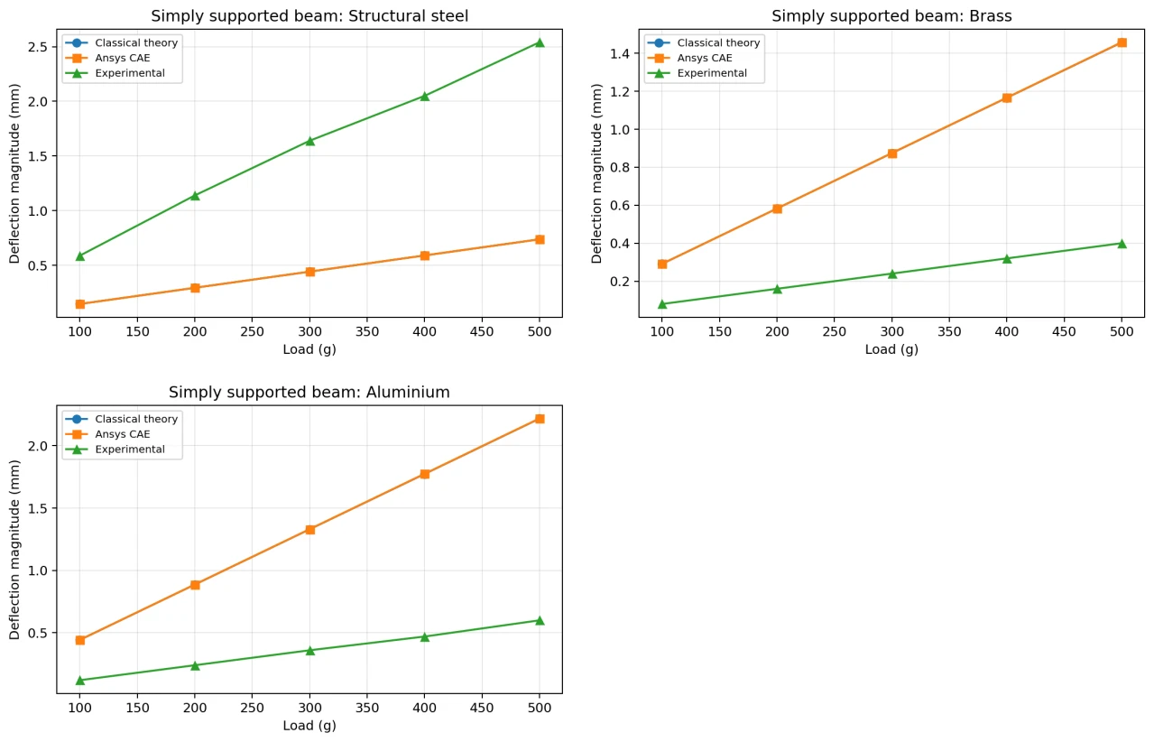
This investigation compares three ways of evaluating slender-beam deflection: classical beam equations, Ansys static structural models and experimental readings supplied in the report. Structural steel, brass and aluminium share a rectangular section so that the study can examine material stiffness alongside two boundary conditions. The cantilever is loaded at a defined distance from its fixed end, while the simply supported arrangement uses a central load between pin and roller supports. Applied masses are converted to forces, theoretical deflections are calculated, and matching linear elastic models are solved over the loading range. The finite element results track the classical calculations closely, including the expected ordering of steel, brass and aluminium stiffness. The report also identifies an important discrepancy: the supplied experimental values are approximately linear with load but do not follow that material ordering. Rather than treating this as successful physical validation, the discussion examines fixture compliance, gauge zero error, material labelling and section measurement as possible causes. The project demonstrates a comparison method and the use of deformation fields to inspect a model, while preserving the need to repeat or verify the experimental setup before using those measurements for design acceptance.
The engineering challenge
Build equivalent analytical and finite element beam cases, then distinguish numerical agreement from the conflicting trends in supplied experimental data.
Engineering approach
- Calculate second moment of area and convert applied masses to forces.
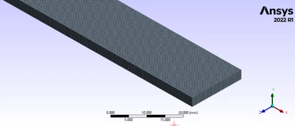
- Configure matched linear elastic materials, geometry and support conditions in Ansys.
- Solve directional deformation for cantilever and simply supported cases.
- Compare load-deflection curves and percentage differences across all three materials.
- Investigate experimental discrepancies and document the limits of the comparison.
Results & observations
Reported Ansys deflection magnitude at the 500 g loading case, versus 1.4781 mm from theory.
Reported Ansys-versus-theory difference at 500 g.
Reported simply supported Ansys magnitude at 500 g, versus 2.2171 mm from theory.
Reported cantilever experiment-versus-theory difference at 500 g; the report calls for checking the test setup.
Features & capabilities
- Three-material comparison
- Cantilever and pin-roller supports
- Static structural FEA
- Directional deformation plots
- Theory-versus-FEA checks
- Experimental discrepancy analysis
Software & engineering tools
Ansys Mechanical, Euler-Bernoulli beam theory, Experimental data comparison