Project brief
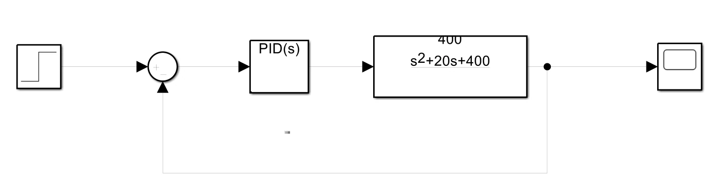
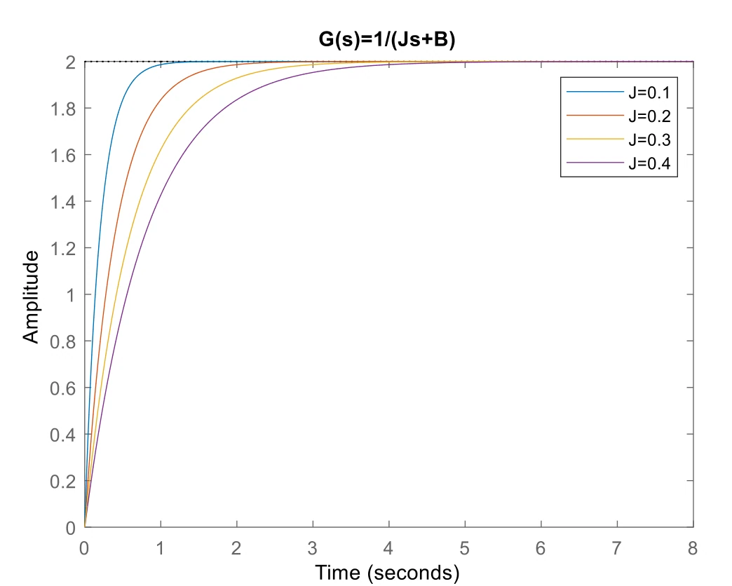
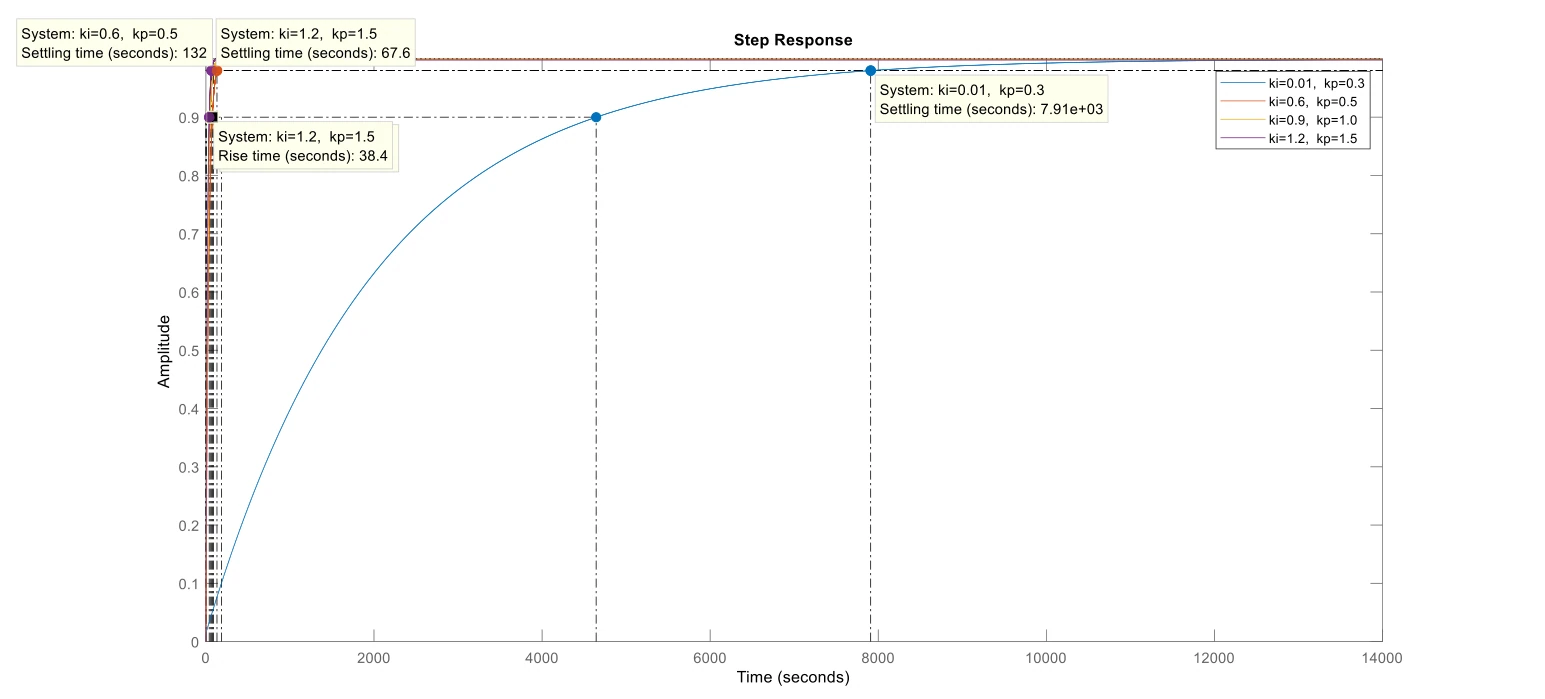
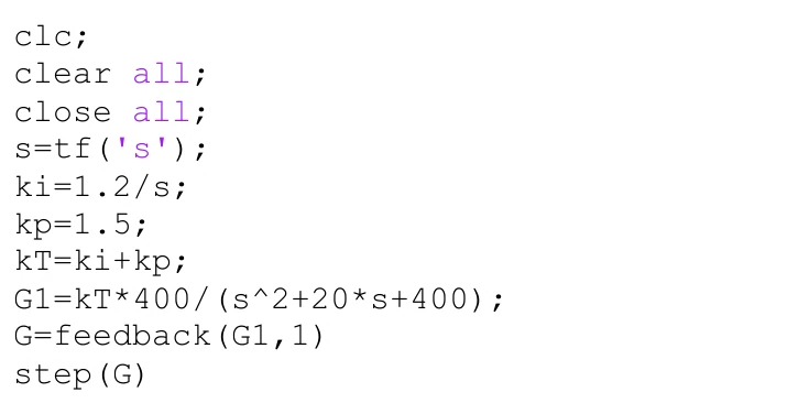
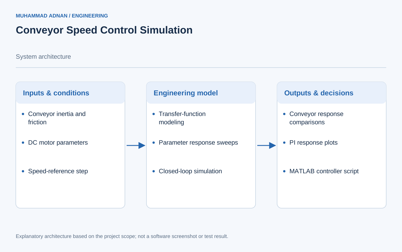
This project explores a conveyor speed-control model using analytical equations, MATLAB scripts and a Simulink feedback diagram. The system is divided into a conveyor load, a variable-speed DC motor and an incremental rotary encoder. The report forms transfer-function representations from inertia, friction, electrical parameters and torque relationships, then uses MATLAB to examine individual and combined responses. One clear parameter study varies the conveyor inertia across four values while holding the friction term fixed; the plotted responses show slower transients as inertia increases. A second study compares four proportional–integral gain pairs using MATLAB feedback and step functions. The document then presents a separate second-order plant example, the corresponding controller code and a Simulink model connecting a step input, summing junction, controller, transfer function and output scope. These software artifacts provide a traceable path from model assumptions to simulated behavior. The source includes numerical and algebraic inconsistencies in parts of its handwritten analysis, so the portfolio account is limited to the models, parameter settings, code and figures that are directly documented. It does not treat the exercise as a validated conveyor commissioning result. The work demonstrates subsystem decomposition, parameter sweeps, elementary controller comparison and equivalent scripted and block-diagram representations of a feedback loop.
The engineering challenge
Connect conveyor mechanics, motor dynamics and speed feedback in a software model that makes the effect of inertia and controller settings visible.
Engineering approach
- Separate the conveyor, DC motor and encoder into model components.
- Construct the documented transfer functions with MATLAB tf objects.
- Compare conveyor step responses for four inertia values while fixing friction.
- Apply four PI gain pairs to a unity-feedback model and compare their plotted responses.
- Represent the later controller and second-order plant example in both MATLAB code and Simulink.
Results & observations
Four documented values, in increments of 0.1, are plotted with B = 0.5; larger inertia gives a slower transient in this model.
The source code compares proportional gains 0.3, 0.5, 1.0 and 1.5 with integral gains 0.01, 0.6, 0.9 and 1.2 respectively.
The supplied implementation applies these gains to the separate plant 400/(s² + 20s + 400).
The report contains executable-style scripts, plotted response comparisons and a closed-loop block model.
Features & capabilities
- Subsystem transfer functions
- Conveyor inertia sweep
- DC motor representation
- PI gain comparison
- Unity-feedback simulation
- Simulink block model
Software & engineering tools
MATLAB, Simulink, Control System Toolbox functions, tf, feedback, step, pzmap