Project brief
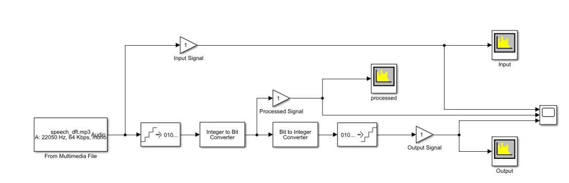
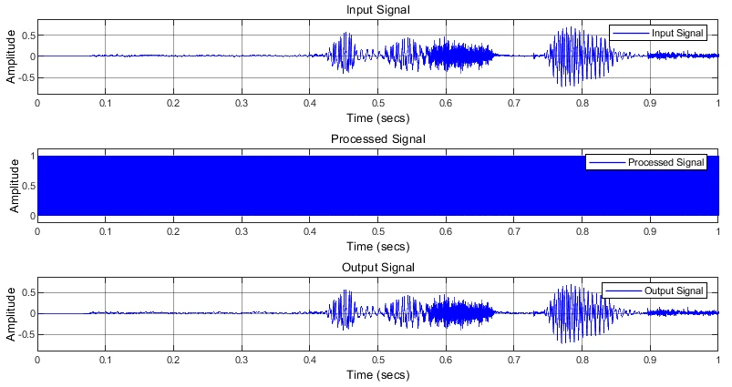
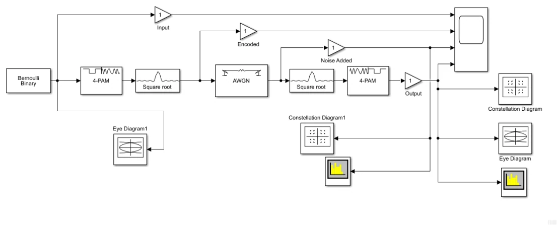
This project builds a set of communication-system experiments in MATLAB and Simulink, following signals from generation through encoding, a noisy channel and reconstruction. The first study digitizes an audio sample and compares input, processed and recovered waveforms alongside their spectra. Two quantization settings are discussed, giving the report a concrete way to explore the link between representation and signal reconstruction. Subsequent models use pulse-amplitude modulation and phase-shift keying with two, four and eight symbol states. Each chain includes observation points for the input, encoded signal, noise-added signal and recovered output. A further model adds square-root raised-cosine filtering at the transmitter and receiver and exposes time scopes, constellation displays, eye diagrams and spectrum analyzers. The project demonstrates the practical assembly of simulation blocks and the use of multiple views to inspect the same communication process. Its strongest evidence is the set of original model diagrams and analyzer captures, including a speech waveform whose broad shape is retained after reconstruction. The report also supplies theoretical error-rate scripts, but implementation inconsistencies prevent treating those plots as a validated ranking of modulation schemes. The portfolio case therefore focuses on the documented signal-processing workflow and displayed simulation behavior, with each numeric analyzer reading understood as specific to its recorded setup.
The engineering challenge
Build comparable transmission chains and inspect how quantization, channel noise and filtering affect the signal at each stage.
Engineering approach
- Digitize an audio sample with integer/bit conversion blocks and reconstruct the output signal.
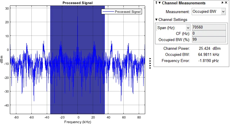
- Inspect time-domain traces and occupied-bandwidth measurements before and after processing.
- Configure PAM and PSK links with M = 2, 4 and 8 and add an AWGN channel.
- Insert square-root raised-cosine filters in a four-level PAM link.
- Use scopes, spectra, constellation plots and eye-diagram instruments to compare the recorded runs.
Results & observations
The report presents speech-digitization results for these two encoding settings.
Separate PAM and PSK models are documented at each stated order.
Occupied-bandwidth reading visible in the recorded eight-bit processed-signal spectrum; this is a run-specific analyzer result.
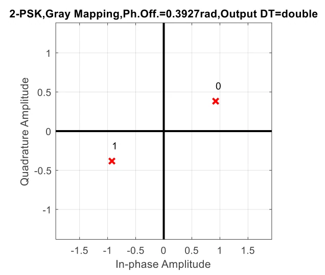
Phase offset shown in the original two-state PSK constellation figure.
Features & capabilities
- Speech quantization and reconstruction
- PAM and PSK models
- AWGN channel simulation
- Raised-cosine pulse shaping
- Time and frequency analysis
- Constellation inspection
Software & engineering tools
MATLAB, Simulink, Spectrum Analyzer, Time Scope